
Table of Contents
 This page is not fully translated, yet. Please help completing the translation.
(remove this paragraph once the translation is finished)
Signavio Onboarding Example
In this chapter, modelling using Signavio will be explained using an example. The detailed documentation for Signavio is found here
1. Log-in

The user e-mail address is used to log into the user profile. If the user doesn't have an account yet, an account for access may be created under “Registration”.
In order to do this, a free license is needed. For questions regarding available licenses, please contact the respective administrator.
2. Create a new model
Next, a new model must be created. In this model, the process steps are defined. This model is then exported as a process definition.

- Select “New”
- Select “Human Workflow for TIM (jPDL)“
- A new browser tab opens, in which a new, empty process model is located. This new model may be changed according to the user's needs
3. Create and edit the process model
The following process should be used as an easy and concrete example to show the modelling possibilities in TIM. This example deals with a so-called onboarding/hiring process, which is relevant for every company.
This section describes the basic functions for working with the process models:
- Create new model
- Edit process model
- Open and save diagrams
First steps
To start the process model, the active departments and/or company areas should be determined. This is done using so-called pools or swim-lanes, also known as lanes. A pool is superordinate organizational unit, which is made up of multiple lanes (representing, for example, departments).
- In order to create a pool, the user clicks and drags the pool symbol from the left channel in the modeling interface. :

- As soon as the user double-clicks in the area of the pool separated to the left, a text field appears, with which the pool may be given a title. In this case the pool is comprised of one superordinate company.
- This example is limited in scope to two swimlanes (departments). However, any number may be created. To create more lanes, click and drag the symbol for lanes from the left column and release the mouse once the mouse is positioned over the pool description. Now, the lane is integrated into the pool. The individual lanes may, in the same manner as the pool, be renamed by double-clicking on the lane caption. In this case, a lane is made for the personnel (“Personal”) department and the IT-department (IT).
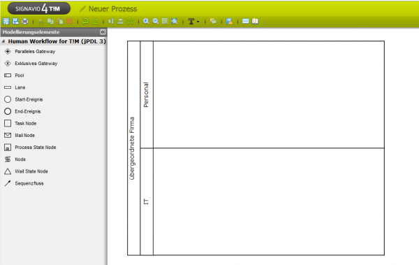
- Every process requires exactly one starting event in order to clearly define at what point the process should begin. This may be taken from the left column in the diagram surface. In this case, the process begins with the personnel department.
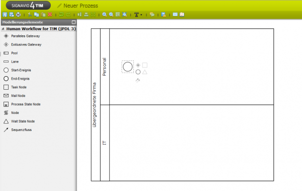 As soon as elements are present in the diagram, the context-sensitive menu may be used to add new elements. This menu is located to the right of the currently selected element. The other way to add new elements is to drag the element from the left column onto the diagram surface. A green check appears under the mouse to show if the element can be dropped into its current position on the screen. If not, a red symbol appears. This can be used, for example, to prevent elements from being added on top of one another in the diagram.
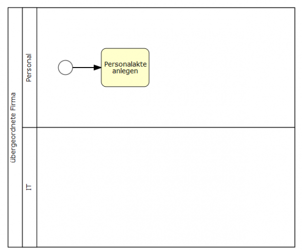
For many elements, the caption may be altered by double-clicking on it.
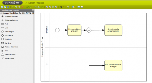
- In the first step, the command “create personal file” should be executed. For this, a task node for one of the two options must be created, which takes place after the starting event. This task node must then be connected to the starting event via a transition.


AND junction
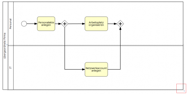
Using an “AND” junction, multiple process steps will be completed at the same time. All of the given process steps must be completed before the process continues past this parallel-splitting of the process. In this example process, a parallel conjunction, with multiple concurrent activities, takes place after the first activity is completed.
- First, the “AND” symbol is dragged from the left column onto the diagram and connected to the activity by means of the context-sensitive menu.
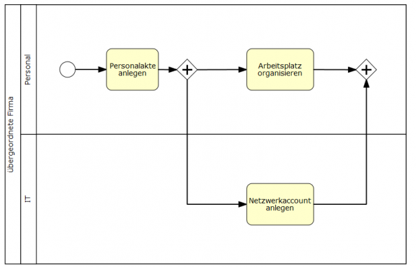
- Now, two new activities, one for the personnel department and one for the IT department, are created and connected with the “AND” symbol. It is possible to create more than two parallel activities if necessary. In this example, the personnel department is given the activity “organize workplace” and the IT department is given the activity “create network account”. If the context-sensitive menu of the AND gateway is used to create new activities, these will be automatically linked.
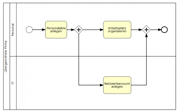
- Opened “AND” connections must be closed at the end so that the process can continue to the next activity. For this, a new AND must be added to the diagram at the position there the parallel paths should end.
- Now, the process is finished. In order to make this apparent, an ending event should be added at the appropriate point in the diagram.


Setting attribute values using the attribute editor
Using a column on the right edge of the editor, the attributes may be customized. The button may be used to show or hide the attribute menu. Now, the attributes of the selected object within the process can be shown. If no object is selected, the general process attributes will be shown.

Attributes
The TIM specifications show only a portion of the attributes, which can be changed using the attribute editor. In any case, only a few of the attributes have any noticeable effect.
| <100% 300px> | |
| Activity attribute | Description |
|---|---|
| Name Mandatory | Name of the activity. Here, no special characters may be used. |
| Duration | Entering and changing of time durations. Format: HHMM Ex.: 1 hour = 0100, 10min = 0010 |
| Tasks Mandatory | Using the dialog behind the points, multiple tasks may be given for a single activity. |
| Event | Here, so-called action handlers for the activity may be integrated.]] |
| <100% 300px> | |
| Activity attribute | Description |
|---|---|
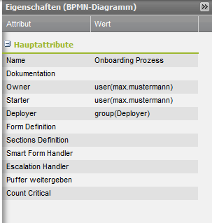
| Name Mandatory | Name of the process being shown after the deployment in TIM. |
| Documentation | Description of the definition. This is later shown in TIM as part of a Tooltip and in a definition report. |
| Starter Mandatory | Here, a user or group, which is able to start instances from this process, is given. i.e. user(john.doe) / group(pm) |
| Owner Mandatory | Here, the person or group, which later is viewed as the “owner” of the process in TIM, is given. “owner” is the term used for the person which is primarily responsible for the process, meaning that he/she oversees and may change the process. |
| Deployer Mandatory | Here, a person or group, which can later deploy the process in TIM, is given. |
| Form Definition | Here, the definition of the Smartform is given. |
After this short overview of the important attributes, the example process will be configured.
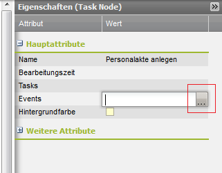
In essence, every activity must have a unique name and at least one task attached to it. An optional working time may also be included.
- Firstly, the activity attributes “create personnel file” is edited. For this, the activity must be marked and the attribute bar must be used. The previously-given name will be adopted in this window.
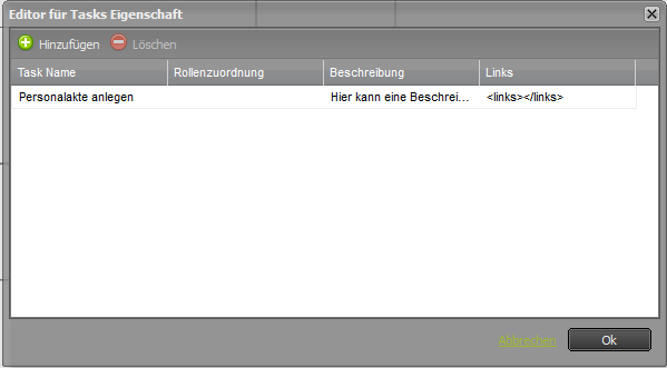
- A task MUST be created within an activity in order to be able to be completed in TIM. Here, clicking on Tasks is used.
- A new pop-up window appears. By clicking on “add” a new task can be entered. Any number of tasks may be created, all of which must be completed before the activity is counted as complete.
- This step must be followed for all activities.


Additionally, process attributes must be created. It is also important here that the process receives a distinct name. The attribute owner, starter, and deployer must also be designated.
- By clicking on an empty position within the diagram, the process attributes may be edited. Now, the rolls must be assigned.
- Lastly, the roll distribution must be defined within the swim lanes. This is also done using the attribute menu, found by clicking within the desired swim lane.

After making these changes, a deployment check may be run.
Deployment Check
Before a process is released, a deployment-check may be run. This proofs if all of the settings needed for a successful deployment have been made and if the process is viable to run in its current state. The deployment check is run by clicking on the corresponding button:

Now, various symbols are blended into the process graphic. By running the mouse over the symbols, erroneous areas may be identified. There are two types of messages:
- Warning : indicates that the model is not-yet complete. For instance, if no duration was attached to a task. This has no effect on the success of the deployment step, but rather gives tips on how to increase the quality of the process.
- Error : indicates that an essential step was not completed, for instance, that a roll assignment was not defined or an element was left unnamed. The process is thus not allowed to be deployed in TIM..

OR (XOR) junction
OR junctions, unlike AND junctions, do not contain parallel paths. Rather, a decision must be made as to which path should be followed. Only the tasks associated with the chosen path will be distributed. The path is chosen by the executor of the previous task before the fork. The choice is supplied to the system through a pop-up window.
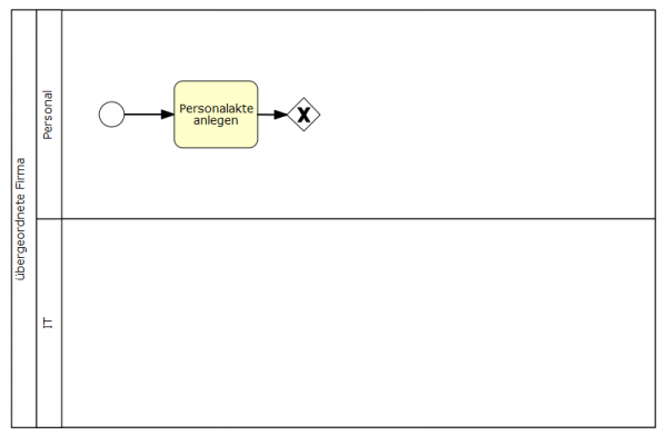
- In order to expand the example at hand, the ending event is deleted by selecting it, then using the “delete” symbol in the Signavio's uppermost editing strip. Next, the area of the pool has to be expanded in order to accommodate the next steps in the process. This is done by clicking on the pool, then dragging the lower corner of the window until the desired size is reached.
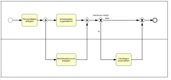
- Now, an XOR Element is placed following the AND element. In order to clarify what decision is to be made, the element may receive a caption (i.e. Hardware needed?). A closing XOR is then added to end the process.
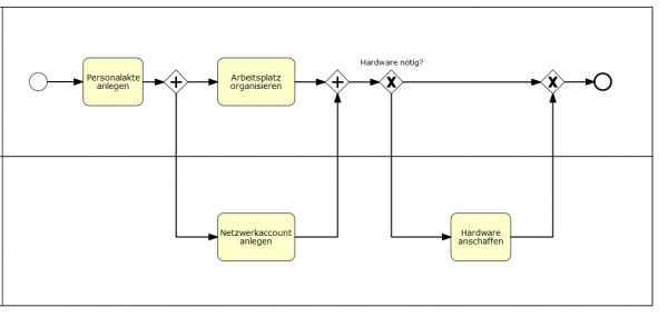
- Because the process must nay make a decision as to which path to follow, it is possible to label both paths in order to clarify which path belongs to which decision. The two arrows may be labeled by double-clicking on them. In this case “no” leads to the ending event and “yes” leads to the activity “Get Hardware”.
- In order for TIM to properly determine which path should be taken, the attributes must be properly tended to. For this, the attributes menu of the arrow must be opened and given a technically unambiguous name in order to make the assignment clear.


Deployment
The process deployment in the TIM-mask environment occurs after the option “Deploy TIM” has been selected from the menu. In order to deploy the process, the user must have the roll of Deployer in the TIM user administration.

After giving the user name and password, the process is deployed by clicking on the button “deploy”.