
Table of Contents
iGrafx Onboarding Example
1. Opening the application
This chapter will give an introduction to modeling with iGrafx by using an example. Detailed documentation for iGrafx can be found here. When opening the program, the following screen will appear:

2. Create a new model
In the ext step, a new model must be created. This model will define the individual steps in our process. Afterwards it can be exported as a process definition. After clicking the button for a new model, this window opens up:

For this example, we use a BPMN Multi-Lane Collaboration diagram.
3. Create and edit process models
The following example is meant to show the different possibilities to model and design processes in iGrafx in combination with TIM. The scenario is a so- called “onboarding procedure” for a new employee, which is a process known to any company.
This paragraph explains the basic functions for working with process models:
- Create a new model
- Editing process models
- Opening and saving diagrams
First steps
1. When starting a process model, all involved departments and/or company parts should be defined. This will be managed by so called pools and swimlanes, also simply called lanes. A pool is a superior unit and and the single lanes represent subzones, e.g. departments in the company. Since we chose the template with more Swimlanes, there are already two lanes and the necessary starting event in our diagram, which has to be unique in the process model. By right clicking the already existing pool it is possible to open the department manager. This manager makes it possible to add new Swimlanes to the pool.
 2. In order to rename the swimlanes, the desired element has to be selected and then clicked. Now it is possible to individualize the label. In this case the pool stands for a superior company and the lanes stand for departments in this company. On the one hand there is the Human Resources Department (“HR”) and on the other hand there is the IT department (“IT”).
  The start event is already placed in the diagram, so it doesn't have to be added separately. if this were to be necessary, it could be added by clicking the corresponding symbol in the left band. The starting event (symbol) can now be placed in the diagram by clicking the desired destination.
  3. For the first step, the Task “create personal file” should be processed. A task node has to be placed behind the start event in order to reach this goal. By selecting the task node symbol in the left band, followed by a click in the diagram, the task is added to the process model. The labeling works similar to the labeling of the swimlanes, by double-clicking. For the next step the start event has to be connected with the task node. This connection is called a “transition”. This can be managed by clicking and holding on the starting event and then moving the mouse onto the task node.
AND Gateway
With an “AND” gateway it is possible to execute multiple steps of a process at the same time. The parallel gateway waits for all tasks inside to be finished before going on. In this example there are two tasks to be done at the same time; one for the HR and one for the IT department.
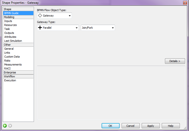
- The first step is to select the diamond symbol from the left band and place it in the diagram. After placing it, it's type must be changed. This is done by right-clicking it and choosing “Properties”. Now the gateway type can be changed to Parallel:
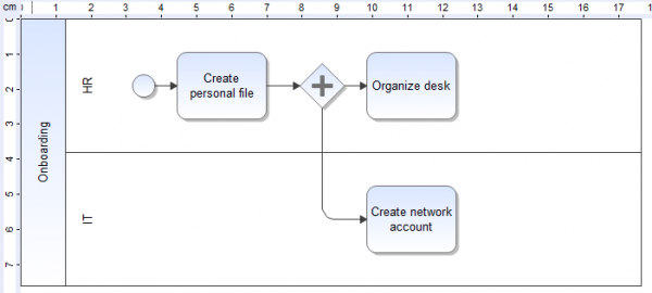
- Now, two new activities can be placed into the HR and the IT lane and connected with the AND. More than two tasks may also be added at the same time. The HR department now gets the task to “organize the desk”, meanwhile the IT department should take care of “creating a network account”:
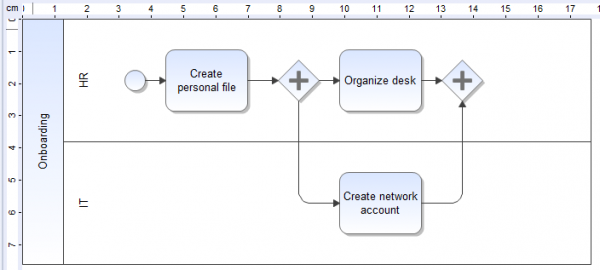
- A forking AND gateway has to be closed at the end so that the process is able to go on with the next tasks. Therefore a new AND gateway has to be added to the diagram and placed at the point where the parallel part should end:
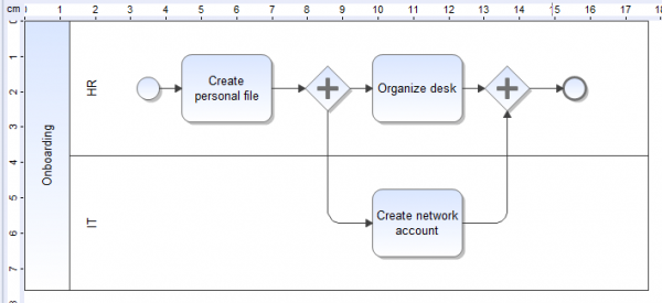
- The process flow is finished so far, but you an end event has to be added in order to show where the process terminates:


Defining and editing attributes
A process needs different attributes in order to be able to run. These attributes can be created or edited by right-clicking on an element and choosing the properties. Different menu options are shown for the current element. The attributes that are most relevant to TIM are under the “Execution” group. In the image we see the general attributes for a process, which can be found in the properties of the start event.

Attributes
| Attribute | Description |
|---|---|
| Description | Description of the process, which will later be shown in TIM (tooltip and process report). |
| Starter Mandatory | Here a group or a user, who is allowed to start instances of a process definition, e.g. user(john.doe), group(pm) is entered. |
| Owner Mandatory | Here a group or a user who “owns” the process in TIM is entered. “Owner” means that this person is responsible for the process |
| Deployer Mandatory | Here a group or a user who is allowed to deploythe process in the TIM system is entered. |
| Smartform | Here the definition of the smartform is entered. |
After this short overview about the attributes that are necessary, the example process may be continued. Basically every activity must have its own unique name. If no task is explicitly defined for the activity, the systems generates a task with the name of the activity. With the aid of the properties menu one or more tasks may be added for an activity. Optionally, the duration of an activity may be entered. In this case a task is added to the “Create Personal File”.
- First the properties menu for this activity has to be opened.
- By clicking the green “Plus” new tasks can be added to the list. These are the tasks that are delegated to the specific employees, who will be responsible to complete them.
- An additional window opens in which the task can be configured. At first, a name must be entered. In addition, there can be an assignment to a special group or user, which overwrites the assignment of the swimlanes. The description field is for further and more detailed information on this task, which will be shown during process execution. It is also possible to add links .

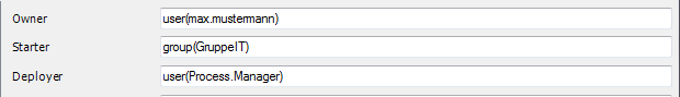
Now the general attributes have to be defined. Owner, Starter and Deployer are needed at this point.
- This can be done by the properties menu of the start event
- Lastly, the swimlanes need an assignment definition, so that its clear who is going to be the user responsible for finishing the tasks inside the swimlane.

After these changes a deployment check is executed.
Deployment Check
Before publishing a process it is possible to do a deployment check. This check shows if all settings are inserted and if the process was able to run as currently configured. The deployment check can be accessed in the following menu: 
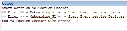
There are two possible ways this check can end:
- There is an error. This will be displayed in the output area of iGrafx.
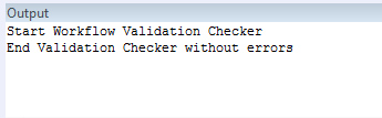
- There are no errors. Consequently a positive message will show up, which implies that the process is ready to be deployed.


XOR (exclusive) Gateway
When running through an XOR/exclusive Gateway, not all outgoing transitions are followed, in contrast to the AND gateway. So there must be a decision which defines which path is followed; only the tasks on this path are to be completed. That decision is made by the user who finishes the last task before the process enters the XOR Gateway. This can be done by a popup, which shows all possible decisions.
- In order to extend the process, the ending event must be deleted. This happens by selecting it and pressing the delete key. The resizing of the pool happens automatically when adding an element to the right border of it.
- Behind the joining AND gateway, a XOR element has to be added. To clarify what kind of decision has to be made, this XOR can be labeled like all the other elements (e.g. “Hardware necessary?”). Finally we end the process by adding the end element.
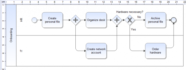
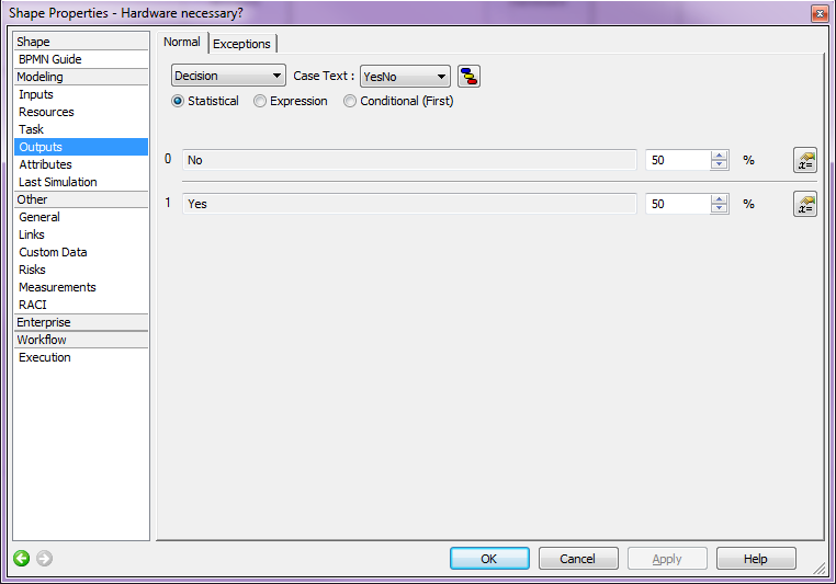
- It is possible to label the transitions in order to clarify which way belongs to which decision. By default, one way gets labeled with “yes” and one with “no”; however, this can be customized. In this case the way denoted 'yes' leads to the activity “Order Hardware” and the other one leads to “archive personal file”. The transition can be adapted in the properties of the XOR gateway.


Deployment
The publishing (Deployment) of the process onto the TIM system happens by choosing the option “Publish As” from the menu. For this, the user needs the role Deployer in the TIM user administration.


After entering the username and the password the process can be published by clicking “Deploy Process”. In the output window a message about the success of the deployment is shown.